margin:0; color:#ff66e1; font: x-small "Trebuchet MS", Trebuchet, Verdana, Sans-serif; font-size/* */:/**/small; font-size: /**/small; text-align: center; } a:link { color:#6131BD; text-decoration:none; } a:visited { color:#000033; text-decoration:none; } a:hover { color:#000000; text-decoration:underline; } a img { border-width:0; } /* Header ----------------------------------------------- */ #header-wrapper { width:660px; margin:0 auto 10px; border:1px solid #e1771e; } #header-inner { background-position: center; margin-left: auto; margin-right: auto; } #header { margin: 5px; border: 1px solid #e1771e; text-align: center; color:#0066CC; } #header h1 { margin:5px 5px 0; padding:15px 20px .25em; line-height:1.2em; text-transform:uppercase; letter-spacing:.2em; font: normal bold 218% Times, serif; } #header a { color:#0066CC; text-decoration:none; } #header a:hover { color:#0066CC; } #header .description { margin:0 5px 5px; padding:0 20px 15px; max-width:700px; text-transform:uppercase; letter-spacing:.2em; line-height: 1.4em; font: italic normal 86% Verdana, sans-serif; color: #341473; } #header img { margin-left: auto; margin-right: auto; } /* Outer-Wrapper ----------------------------------------------- */ #outer-wrapper { width: 660px; margin:0 auto; padding:10px; text-align:left; font: italic normal 121% Times, serif; } #main-wrapper { width: 410px; float: left; word-wrap: break-word; /* fix for long text breaking sidebar float in IE */ overflow: hidden; /* fix for long non-text content breaking IE sidebar float */ } #sidebar-wrapper { width: 220px; float: right; word-wrap: break-word; /* fix for long text breaking sidebar float in IE */ overflow: hidden; /* fix for long non-text content breaking IE sidebar float */ } /* Headings ----------------------------------------------- */ h2 { margin:1.5em 0 .75em; font:italic normal 95% Courier, monospace; line-height: 1.4em; text-transform:uppercase; letter-spacing:.2em; color:#C3D9FF; } /* Posts ----------------------------------------------- */ h2.date-header { margin:1.5em 0 .5em; } .post { margin:.5em 0 1.5em; border-bottom:1px dotted #e1771e; padding-bottom:1.5em; } .post h3 { margin:.25em 0 0; padding:0 0 4px; font-size:140%; font-weight:normal; line-height:1.4em; color:#000000; } .post h3 a, .post h3 a:visited, .post h3 strong { display:block; text-decoration:none; color:#000000; font-weight:bold; } .post h3 strong, .post h3 a:hover { color:#ff66e1; } .post p { margin:0 0 .75em; line-height:1.6em; } .post-footer { margin: .75em 0; color:#C3D9FF; text-transform:uppercase; letter-spacing:.1em; font: italic normal 78% Trebuchet, Trebuchet MS, Arial, sans-serif; line-height: 1.4em; } .comment-link { margin-left:.6em; } .post img { padding:4px; border:1px solid #e1771e; } .post blockquote { margin:1em 20px; } .post blockquote p { margin:.75em 0; } /* Comments ----------------------------------------------- */ #comments h4 { margin:1em 0; font-weight: bold; line-height: 1.4em; text-transform:uppercase; letter-spacing:.2em; color: #C3D9FF; } #comments-block { margin:1em 0 1.5em; line-height:1.6em; } #comments-block .comment-author { margin:.5em 0; } #comments-block .comment-body { margin:.25em 0 0; } #comments-block .comment-footer { margin:-.25em 0 2em; line-height: 1.4em; text-transform:uppercase; letter-spacing:.1em; } #comments-block .comment-body p { margin:0 0 .75em; } .deleted-comment { font-style:italic; color:gray; } .feed-links { clear: both; line-height: 2.5em; } #blog-pager-newer-link { float: left; } #blog-pager-older-link { float: right; } #blog-pager { text-align: center; } /* Sidebar Content ----------------------------------------------- */ .sidebar { color: #38B63C; line-height: 1.5em; } .sidebar ul { list-style:none; margin:0 0 0; padding:0 0 0; } .sidebar li { margin:0; padding:0 0 .25em 15px; text-indent:-15px; line-height:1.5em; } .sidebar .widget, .main .widget { border-bottom:1px dotted #e1771e; margin:0 0 1.5em; padding:0 0 1.5em; } .main .Blog { border-bottom-width: 0; } /* Profile ----------------------------------------------- */ .profile-img { float: left; margin: 0 5px 5px 0; padding: 4px; border: 1px solid #e1771e; } .profile-data { margin:0; text-transform:uppercase; letter-spacing:.1em; font: italic normal 78% Trebuchet, Trebuchet MS, Arial, sans-serif; color: #C3D9FF; font-weight: bold; line-height: 1.6em; } .profile-datablock { margin:.5em 0 .5em; } .profile-textblock { margin: 0.5em 0; line-height: 1.6em; } .profile-link { font: italic normal 78% Trebuchet, Trebuchet MS, Arial, sans-serif; text-transform: uppercase; letter-spacing: .1em; } /* Footer ----------------------------------------------- */ #footer { width:660px; clear:both; margin:0 auto; padding-top:15px; line-height: 1.6em; text-transform:uppercase; letter-spacing:.1em; text-align: center; } /** Page structure tweaks for layout editor wireframe */ body#layout #header { margin-left: 0px; margin-right: 0px; } -->

Thursday, January 31, 2008

INSTALLING DVD DRIVE


When you are ready to begin installing your new DVDDrive,have plenty of roon on your desk or table towork.Allow enough space to move around and to beable to move the system unit as well.
Check to see if you have ample light.You may want tohave a container to place small screws in.The systemunit cover may have small screws and you don't wantto lose them.
After you have plenty of work space and ample lighting,prepare your mind as well.Make this and every otheradventure of working on your computer educationaland fun.

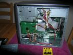
Now go over to www.ultimatepcrepair.com/photos.htmlto familarize yourself with all components inside the PC.Take the time to study the actual components insideyour computer.You'll be glad you did should somethinggo wrong.Follow these steps to install your drive.

REMOVE THE COMPUTER COVER
First Turn off your computer and unplug all peripherals.Take notice of how you unplug or disconnect anydevices.

Second Remove the side panel of the tower system or the cover if you have a desktop.Place the panel in asafe place well out of the way.

Third Before touching anything inside the system unit,remove electrical static charge from your body bytouching a door knob or any unpainted metal surface.

Fourth Remove the new drive from its protective wrapping and take the time to read through the manual.Be sure you have all components and save the boxjust in case it need to be returned.

Fifth Check the jumper settings on the drive to be sureit is set to master.If you are adding this drive as a seconddrive,you will have to set one as master and one as theslave drive.
Your manual should make this procedure quick and fast.A small pair of tweezers can be used to remove thesmall jumper to the correct position.Most drives are setto master by default.

SLIDE NEW DRIVE IN COMPUTER
Sixth Locate the drive bay for the cdrom drive.In mostcases,its at the top of the case.If you are removinganother drive,slide it out partially,disconnect cables,and slide the drive out completely.Take note of thelocation of all connections.
If you are installing a new drive the first time,use asmall screwdriver to pop off the 5.25 inch drive baycover and bezel on the system unit case.
Seventh Slide the new drive in partially and connectthe data,sound,and power cables to the rear of thedrive.Slide the drive in completely and use smallscrews to secure the drive to the case.
In some cases,the drive is secured to the case with theuse of Drive rails.These rails should be mounted onthe old drive if you had to remove one.Check the drive'smanual if your new drive came with side rails.
When connecting the cable,carefully graps the cablesby the ends and not the wires themselves.Carefullybut firmly push the connectors into their sockets untilyou are certain of a good connection.
If you are installing this drive as a second drive andhave made this drive the secondary or slave drive,connect the drive to the center connector on the Ribbon cable.The master drive must be at the end.
Eighth After all cables are re-connected to the drive andthe drive is secured to the case,replace the system unitcover,reconnect all peripherals.Be sure the faceplate ofthe drive is flush with the front of the computer.

SETUP YOUR NEW DVD DRIVE

Ninth Boot up the computer and in nearly all cases,theoperating system should detect the new drive and install the device driver if necessary.
In most cases,new cdroms and dvd drives will notcome with a cdrom or diskette with a device driver.Windows should install the drive with ease.
Some new drives will come with a cdrom full of software,such as games,music,or movies.Checkthis cdrom for software utilities that you may needto help run and operate your drive.
Tenth Check your new drive to see if Windows hasrecognized it.Click on My Computer and you shouldsee the drives installed.Check for both drives if youinstalled the drive as a second drive.


And that's it.You can now use the drive as a huge data backup.Or you may want to make movies.Whatever the case,check the drive for compatbilitywith other drives.
Take the time to learn absolutely everything aboutthat computer you're reading this with.Quicklymaster the art of installing not just the dvd drive,but all drives and other components.

CPU PACKAGE TYPE


1.)S.E.C.C. Package Type.S.E.C.C. is short for Single Edge Contact Cartridge. To connect to the motherboard, the processor is inserted into a slot. Instead of having pins, it uses goldfinger contacts, which the processor uses to carry its signals back and forth. The S.E.C.C. is covered with a metal shell that covers the top of the entire cartridge assembly. The back of the cartridge is a thermal plate that acts as a heatsink. Inside the S.E.C.C., most processors have a printed circuit board called the substrate that links together the processor, the L2 cache and the bus termination circuits. The S.E.C.C. package was used in the Intel Pentium II processors, which have 242 contacts and the Pentium® II Xeon™ and Pentium III Xeon processors, which have 330 contacts.


2.)S.E.C.C.2 Package Type.The S.E.C.C.2 package is similar to the S.E.C.C. package except the S.E.C.C.2 uses less casing and does not include the thermal plate. The S.E.C.C.2 package was used in some later versions of the Pentium II processor and Pentium III processor (242 contacts).


3.)S.E.P. Package Type.S.E.P. is short for Single Edge Processor. The S.E.P. package is similar to a S.E.C.C. or S.E.C.C.2 package but it has no covering. In addition, the substrate (circuit board) is visible from the bottom side. The S.E.P. package was used by early Intel Celeron processors, which have 242 contacts.


4.)PPGA Package Type.PPGA is short for Plastic Pin Grid Array, and these processors have pins that are inserted into a socket. To improve thermal conductivity, the PPGA uses a nickel plated copper heat slug on top of the processor. The pins on the bottom of the chip are staggered. In addition, the pins are arranged in a way that the processor can only be inserted one way into the socket. The PPGA package is used by early Intel Celeron processors, which have 370 pins.
5.)PGA Package Type.PGA is short for Pin Grid Array, and these processors have pins that are inserted into a socket. To improve thermal conductivity, the PGA uses a nickel plated copper heat slug on top of the processor. The pins on the bottom of the chip are staggered. In addition, the pins are arranged in a way that the processor can only be inserted one way into the socket. The PGA package is used by the Intel Xeon™ processor, which has 603 pins

CPU SOCKET


A CPU socket or CPU slot is a connector on a computer's motherboard that accepts a CPU and forms an electrical interface with it. As of 2007, most desktop and server computers, particularly those based on the Intel x86 architecture, include socketed processors.Most CPU-sockets interfaces are based on the pin grid array (PGA) architecture, in which short, stiff pins on the underside of the processor package mate with holes in the socket. To minimize the risk of bent pins, zero insertion force (ZIF) sockets allow the processor to be inserted without any resistance, then grip the pins firmly to ensure a reliable contact after a lever is flipped.As of 2007, several current and upcoming socket designs use land grid array (LGA) technology instead. In this design, it is the socket which contains pins. The pins contact pads or lands on the bottom of the processor package.In the late 1990s, many x86 processors fit into slots, rather than sockets. CPU slots are single-edged connectors similar to expansion slots, into which a PCB holding a processor is inserted. Slotted CPU packages offered two advantages: L2 cache memory could be upgraded by installing an additional chip onto the processor PCB, and processor insertion and removal was often easier. However, slotted packages require longer traces between the CPU and chipset, and therefore became unsuitable as clock speeds passed 500 MHz. Slots were abandoned with the introduction of AMD's Socket A and Intel's Socket 370.

Thursday, January 17, 2008

ASSIGNMENT #3: MOTHERBOARD FORM FACTORS

LPX

LPX (Low Profile eXtension), originally developed by Western Digital, was a loosely defined motherboard format (form factor) widely used in the 1990s.
There was never any official LPX specification, but the design normally featured the main I/O ports mounted on the back of the motherboard (something that was later adopted by the ATX form factor), and a riser card in the center of the motherboard, on which the PCI and ISA slots were mounted. Due to the lack of standardised specification, riser cards were seldom compatible from one motherboard design to another, much less one manufacturer to another. The internal PSU connector was of the same type used in the AT form factor; most LPX cases were compatible with AT power supplies, though some used models that were smaller than standard, and usually manufacturer-specific.
The specification was very popular in the early-mid 90's, and briefly displaced the AT form factor as the most commonly used. However, the release of the Pentium II in 1997 highlighted the flaws of the format, as a good airflow was important in Pentium II systems, owing to the relatively high heat dispersal requirements of the processor. LPX systems suffered a restricted airflow due to the centrally placed riser cards. The introduction of the AGP format further complicated matters, as the design not only increased the pincount on riser cards, but it limited most cards to one AGP, one PCI and one ISA slot, which was too restrictive for most users. Some lower-quality LPX boards didn't even feature a real AGP slot, but simply used a physical AGP slot and connected it to the PCI bus. This was seldom noticed however, as many "AGP" graphics cards of the time were in fact PCI cards internally, and did not take advantage of the features offered by AGP.
LPX was phased out around 1998. NLX was the intended successor, though many manufacturers chose MicroATX or proprietary motherboard formats instead.

ATX


Release 2.01 of the ATX Specification

(February 1997) makes minor adjustments to Release 2.0, which incorporated a number of new features, additional requirements, and clarifications. These changes take into account support for the next generation of ATX motherboards, while maintaining compatibility with the first generation. Readers should examine their combination of motherboard, power supply and chassis needs to determine whether they require the additional features found in Release 2.01
The ATX specification has been written as a specification for the PC industry, designed to add value to the PC. It defines a new PC form-factor that will allow PC manufacturers to build products more cheaply, improve ease of use and serviceability, and incorporate new and exciting I/O features with ease. The ATX form factor is essentially a Baby-AT baseboard rotated 90 degrees within the chassis enclosure and a new mounting configuration for the power supply. In this way, the processor is relocated away from the expansion slots, allowing them all to hold full length add-in cards. ATX defines a double height aperture to the rear of the chassis which can be used to host a wide range of on-board I/O. Only the size and position of this aperture is defined, allowing PC manufacturers to add new I/O features (e.g.; TV input, TV output, joystick, modem, LAN, audio, etc.) to systems that will help them differentiate their products in the marketplace, and better meet the needs of end users

NLX


NLX is a new low profile motherboard form factor designed to improve upon today’s low profile form factors and to adapt to new market trends and PC technologies. NLX does the following:
*The add-in card riser is located at the right edge of the motherboard (as viewed from the front).
*The processor is located at the front, left section of the motherboard, improving thermal and clearance issues.
*Taller components such as the processor and tall memory are preferred to be located on the left side of the motherboard, allowing the I/O slots to hold full length add-in cards in many system configurations.
*At the back of the motherboard (as viewed from the front), the I/O connectors are stacked single and double high to support more connectors.